Course Duration: 3 Month
TIME: 3 Hours Daily
Topics Cover:
Basic Engineering Draining
Measurement technology
Auto CAD
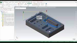
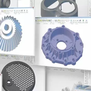
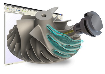
CNC operating for CNC milling with master cam software.
Course Duration: 3 Month
TIME: 3 Hours Daily
Topics Cover:
Basic Engineering Draining
Measurement technology
Auto CAD
CNC operating for CNC milling with master cam software.
Course Duration: 3 Month
TIME: 3 Hours Daily
Topics Cover:
Basic Engineering Draining
Measurement technology
AutoCAD
CNC operating for CNC milling with master cam software.
Basic Engg Drawing
Introduction to Engineering Draining
An engineering drawing, a type of technical drawing, is used to fully and clearly define requirements for engineered items.
Engineering drawing (the activity) produces engineering drawings (the documents). More than merely the drawing of pictures, it is also a language—a graphical language that communicates ideas and information from one mind to another. Most especially, it communicates all needed information from the engineer whodesigned a part to the workers who will make it.
Measurement Technology:
Different type of measurement technology and Instrument like Vernier / Micro meter / Radius Gauge / Thread Gauge etc.
Practical usage with variant components.
Measurement begins with the definition of the measured, the quantity intended to be measured. The specification of a measured requires knowledge of the kind of quantity and a description of the object carrying the quantity. When the measured is defined, it must be related to a measurement standard, the realization of the definition of the quantity to be measured. The measurement procedure is a detailed description of a measurement according to a measurement principle and to a given measurement method.
AutoCAD
File Management / Orthographical Drawing
View, Display, Layer Management /
Symbol Creation Using block / BOM
Isometric Drawing
Annotation and Dimension
Layout Management etc….
Cutting Tool Technology
What is a Cutting Tool?
Two basic types:-
Single Point Cutting Tool:
Multi Point Cutting Tool:
Manual CNC Milling Programming.
Manual CNC Lathe Programming.
Lathe is considered as one of the oldest machine tools and is widely used in industries.
It is called as mother of machine tools. It is said that the first screw cutting lathe was developed by an Englishman named Henry Maudslay in the year 1797.
The primary task of a lathe is to generate cylindrical work pieces. The process of machining a workpiece to the required shape and size by moving the cutting tool either parallel or perpendicular to the axis of rotation of the workpiece is known as turning. In this process, excess unwanted metal is removed. The machine tool useful in performing plain turning, taper turning, thread cutting, chamfering and knurling by adopting the above method is known as lathe.
Master CAM machining / Live CNC Machining with CAM software.